HV Precharge & Bus-Sequencing Controller
Arduino-controlled precharge, bus switchover, and E-stop sequencing for ~1.2 kV DC-DC converter test rigs.
At the McMaster Automotive Resource Centre (Dr. Ali Emadi's transportation-electrification group) I supported three PhD researchers across DC-DC converter, motor-characterization, and dynamometer projects. My main deliverable: Arduino-controlled precharge circuits for two ~1.2 kV DC-DC converter test rigs — sequencing capacitor precharge, bus switchover, and emergency stop so the rigs could be energized without inrush damage.
- Role
- Research Assistant — built, programmed, validated
- Timeline
- Jan — Apr 2026
- Status
- Research
- Stack
- ArduinoHV prechargeBus switchoverE-stopHV safety
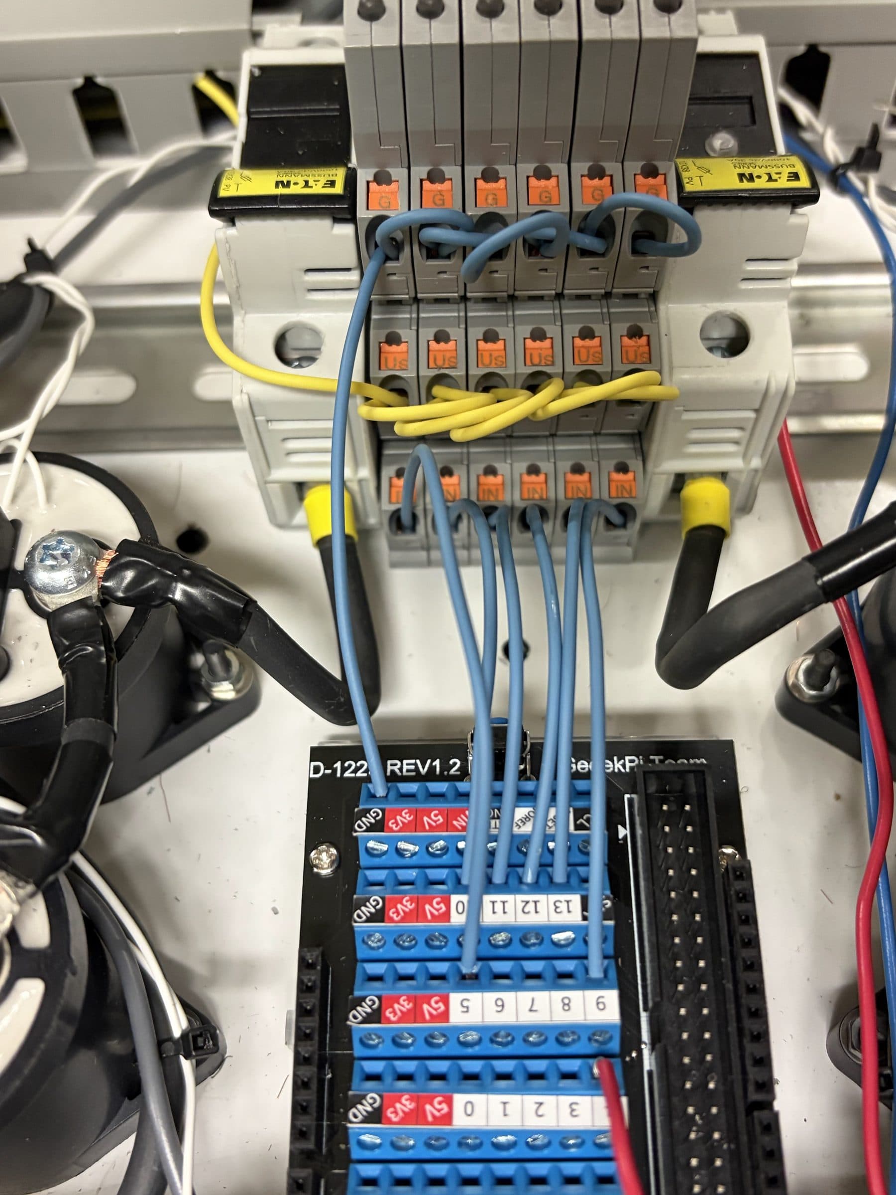
Two converter test rigs at ~1.2 kV
One rig hosted an 11 kW three-port triple active bridge (TAB) converter — 300–700 V input, 890–1250 V high-voltage output, and 36–48 V low-voltage output — researched for 1.25 kV on-board-charger and 48 V auxiliary-power-module applications. Both rigs needed a controlled way to bring their DC links up from a stiff high-voltage source.
A discharged DC link looks like a short circuit
A converter's DC-link capacitance starts at 0 V. Closing a contactor straight onto the source puts the full bus voltage across only the wiring and capacitor ESR, so the inrush is limited by a few milliohms — enough to weld contactor tips, blow fuses, and stress the capacitors. A precharge path inserts a resistor first:
Peak current becomes , and the link reaches over 99 % of the bus after about . Sizing the resistor is a trade between that charge time, the peak current, and the resistor's pulse-energy rating — the stored energy is dissipated in it during every precharge.
Sequencing: precharge → switchover → run, with E-stop from anywhere
The Arduino sequences the rig in a fixed order — precharge the DC link through the resistor, switch the bus over to the main path, then run — and an emergency stop de-energizes the rig from any stage.
- IdleAll paths open
- PrechargeDC link charges through the precharge resistor
- SwitchoverBus moves to the main path; precharge path drops out
- RunConverter under test energized
Technical Documentation
§LV load steps (48 V side)
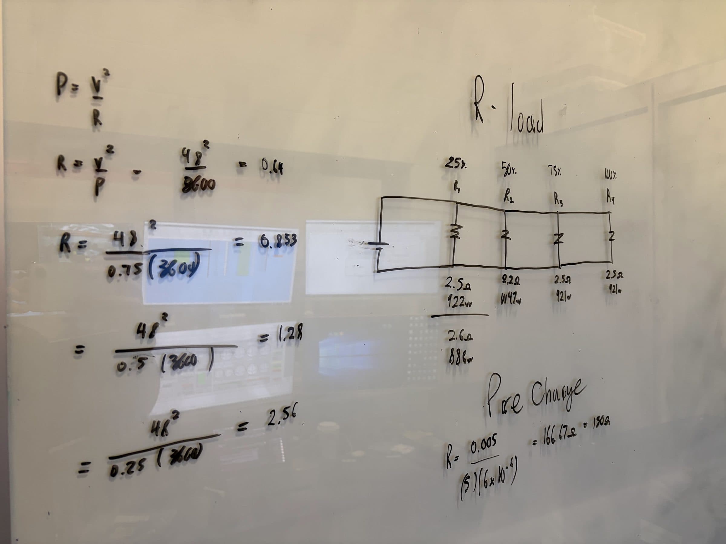
Hand calculation for a 48 V, 3.6 kW resistive load on the low-voltage side, sized in 25 / 50 / 75 / 100 % steps. From :
| Load step | Power | Equivalent R |
|---|---|---|
| 100 % | 3.6 kW | 0.64 Ω |
| 75 % | 2.7 kW | 0.853 Ω |
| 50 % | 1.8 kW | 1.28 Ω |
| 25 % | 0.9 kW | 2.56 Ω |
§Precharge resistor sizing method
Choose a target charge time , set it equal to about five time constants, and solve for the resistance; then check peak current and pulse energy:
§HV safety
I designed and built a ground-bonded HV test enclosure so testing could be done under the lab's formal high-voltage safety procedures, with the emergency stop built into the precharge sequence.
§Other MARC work
- Helped commission a Chevrolet Bolt EV motor on a three-machine dynamometer: built three-phase HV motor cables, machined the motor mount, dogbone, and faceplate, wired sensor and control harnesses, and set up the oil system and dyno software.
- Designed a 2-layer CAN-to-Ethernet adapter PCB in Altium and six custom mechanical parts in CAD, including a carbon-fiber 3D-printed motor oil-pump relocation adapter and a dynamometer wheel-plate spacer.
- Named contributor on a resulting research publication.